Dealkalization of water

What is a Dealkalizer ?

The dealkalization of water refers to the removal of alkalinity ions from water.
Chloride cycle dealkalizers operate similar to sodium cycle cation water softeners.

See : How a Zeolite Water Softener Works ?

Like water softeners, dealkalizers contain ion exchange resins that are regenerated with a concentrated salt (brine) solution - NaCl. In the case of a water softener, the cation exchange resin is exchanging sodium (the Na ion of NaCl) for hardness minerals such as calcium and magnesium.

A dealkalizer contains strong base anion exchange resin that exchanges chloride (the Cl ion of the NaCl) for carbonate, bicarbonate and sulfate. As water passes through the anion resin the carbonate, bicarbonate and sulfate ions are exchanged for chloride ions.


What’s Wrong With Alkalinity?

Dealkalizers are most often used as pre-treatment to a boiler and are usually preceded by a water softener. Alkalinity is a factor that most often dictates the amount of boiler blowdown. High alkalinity promotes boiler foaming and carryover and causes high amounts of boiler blowoff. When alkalinity is the limiting factor affecting the amount of blowdown, a dealkalizer will increase the cycles of concentrations and reduce blowdown and operating costs.

The reduction of blowdown by dealkalization keeps the water treatment chemicals in the boiler longer, thus minimizing the amount of chemicals required for efficient, noncorrosive operation.

Carbonate and bicarbonate alkalinities are decomposed by heat in boiler water releasing carbon dioxide into the steam. This gas combines with the condensed steam in process equipment and return lines to form carbonic acid. This depresses the pH value of the condensate returns and results in corrosive attack on the equipment and piping.

Naturally occurring alkalinity comes in the form carbonate and bicarbonate.  When alkalinity enters the boiler, it breaks down into OH– and CO2.  CO2 (gas) exits with the steam and forms carbonic acid as the steam condenses (pH < 6.0).  Left untreated, low pH water can potentially rot out the condensate network.

Some physical indicators of carbonic acid attack are the thinning of carbon steel piping along the bottom curvature of the pipe, leakage of condensate at points of low wall thickness (ie. threads) and erosion at control points like traps or control valves.


Condensate Chemical Treatment for Alkalinity

Whenever possible, we should strive to “remove rather than treat for” and in order to formulate a proper pre-treatment solution, a thorough understanding of incoming water quality is required..

A common chemical treatment is to add neutralizing amines to the boiler feedwater or steam header.  When the steam condenses, the neutralizing amine will neutralize the effect of the carbonic acid and maintain the pH at an acceptable level to prevent corrosion.  The degree of alkalinity in the boiler feedwater determines amine requirement (ie. the required application rate for volatile amine is likely significantly greater for the boiler operating on rural ground water than the same boiler operating on great lakes surface water)

HVAC - Main parts in order

Different parts of typical AHU

*Mostly all the information presented here are from The Engineering Mindset Youtube Channel.

Supply air, main parts (excluding sensors)

  1. Grille
  2. Damper
  3. Frost protection coil (usually electric coil/heater)
  4. Pre-Filter
  5. Filter
  6. Cooling coil
  7. Heating coil
  8. Humidifier (steam or water mist)
  9. Supply fan (centrifugal or EC type)

Main sensors :
  1. Pressure sensor (Magnelic)
    • Measure pressure before and after the pre-filter and filter
  2. Temperature sensor (Thermistor)
    • Measure temperature before and after coils to adjust heating and cooling load
  3. Humidity sensor
    • Measure humidity to adjust humidifier load
  4. Static pressure sensor
    • Measure static pressure to adjust centrifugal fan speed (when VAD are installed)


1. Grille

Grille prevent animals and waste to enter inside the AHU.


2. Damper


Everything about Pillow Block

Pillow Block VS Flange Block

A Pillow Block is a pedestal used to provide support for a rotating shaft. An anti-friction bearing is contained and mounted inside the pedestal. Pillow Block are also referred to as a Housed Bearing Unit, meaning they are self-contained, greased, sealed and ready for installation on the equipment.

A Pillow Block refers to any mounted bearing wherein the mounted shaft is in a parallel plane to the mounting surface, and perpendicular to the center line of the mounting holes, as contrasted with various types of Flange Blocks or flange units.


Solid VS Split Housing

Pillow Block (solid housing) differ from Plummer Block (split housing). Split type housings are usually two-piece housings where the cap and base may be detached, while solid housing may be single-piece housings. Plummer Block are bearing housings supplied without any bearings and are usually meant for higher load ratings and a separately installed bearing.

The fundamental application of both types is the same, which is to mount a bearing safely enabling its outer ring to be stationary while allowing rotation of the inner ring.


Bearing Type

Pillow block bearings can contain several types of bearings, including :

  • Ball
  • Roller
  • Tapered

Shaft Attachement

Shaft attachment devices can be :

  • Set screw, 
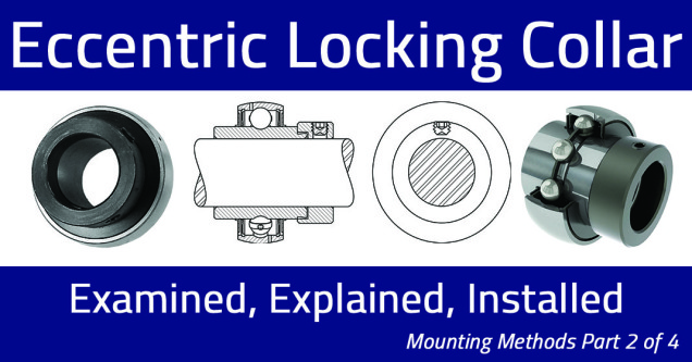
  • Eccentric lock
  • Concentric lock
  • Tapered adapter

Set Screw
  • Easy to Install
  • Lowest Purchase Price
  • Clearance Fit
  • Moderate Shaft Damage*
  • Low to Medium Speed
*Note: this shaft attachment method can cause fretting corrosion, making removal difficult after years of operation


Eccentric Lock

  • Easy to Install
  • Relatively Low Market Price
  • Uni-directional
  • Minor Shaft Damage
  • Low to Medium Speeds
*Note: this shaft attachment method is unidirectional and NOT intended for reversing loads. Eccentric locking collar mounted bearings contact the shaft over a larger surface area compared to setscrew mounted bearings. This can reduce shaft damage and fretting corrosion.


Concentric Lock

  • Easy to Install
  • Minimal Shaft Damage
  • Concentric Grip to the Shaft
  • Provides a More Balanced Effect Ideal for Medium to High Speeds
*Note: this mounting method is helpful to minimize vibration.


Tapered Adapter

Tapered adapter assemblies consist of a tapered adapter sleeve, a lock washer and a lock nut. As the adapter is tightened using a spanner wrench, the adapter is drawn through the bearing and tightened to the shaft. Because the contact of the bearing is evenly distributed around the shaft, it provides the most concentric/ideal fit.


How to Video !


How to classify Cooling Towers


Manufacture Type

The broadest way to classify a cooling tower is by the way it is manufactured. The two primary types are field-erected products (FEP) and factory-assembled products (FAP). 

Field-erected cooling towers typically serve the power and heavy industrial market where the heat rejection required and water volume are very large. Primary construction of an FEP tower typically happens at the site of use. 

Factory-assembled cooling towers are primarily assembled at the manufacturing plant, then shipped and installed at the site of use. FAP towers serve HVAC, light industrial and commercial markets.


Draft Type

Once a manufacture type is determined, a subclassification exists by the method in which air is introduced into the cooling tower. 

There are three ways to bring air into the tower :
  1. Natural draft (FEP only) 
  2. Induced draft
  3. Forced draft. 
Airflow through a natural draft cooling tower is produced by the density differential that exists between the heated (less dense) air inside the stack and the relatively cool (more dense) ambient air outside the tower. Natural-draft cooling towers are primarily used in very large power and heavy industrial applications. 


Induced-draft towers have axial fans at the air discharge of the tower and pull the air in. Induced draft cooling towers are the most common and are used in power, industrial and HVAC markets. 

Forced-draft cooling towers typically use centrifugal fans (blowers) at the air inlet of the cooling tower which push the air through. Forced-draft cooling towers have the advantage of being able to operate against the high static pressures associated with ducting and can be installed indoors, space permitting. Centrifugal fans are less common than axial fans because they can consume twice as much power.


Air Movement

An additional way to sub-classify a cooling tower is the method by which the air and the process water make contact. 

The two classifications are crossflow and counterflow, both of which are used in FEP and FAP cooling towers. 

  1. In a crossflow cooling tower, air travels horizontally across the direction of the falling water. 
  2. In a counterflow tower, air travels in the opposite direction (counter) to the direction of the falling water. 


The type of application usually dictates whether a crossflow or counterflow cooling tower would be better suited for the process. 

In HVAC, an FAP counterflow tower may be preferred for its small footprint, whereas a crossflow tower may be preferred for its maintenance access and better tolerance for cold weather operation. 

In the power and heavy industrial market, an FEP crossflow tower may be preferred for dirty water applications whereas a counterflow cooling tower may be preferred for its higher efficiency in applications with better water quality.


Air/Water Contact Type

Within the FAP category, cooling towers are also classified by air/water contact based on :
  1. Open-loop
  2. Closed-loop design
Closedloop cooling towers (fluid coolers) typically have a smaller singlecell capacity relative to an open tower, but have several advantages. Closed-loop cooling towers keep the process fluids separated and clean. Because the process fluid is in a closed loop, fluids other than water and fluids at much higher temperatures can be cooled.


Summary

There are three primary ways to classify a cooling tower — manufacture type, draft type, and air/water contact. Although there are several different potential combinations from an FAP forceddraft, counterflow, closed-loop cooling tower to an FEP induceddraft, crossflow, open cooling tower, typically the application easily narrows down the best choices to one or two preferred types of cooling towers.


CrossFlow VS CounterFlow Cooling Tower

Crossflow VS Counterflow

Crossflow and counterflow are two ways to describe how air moving through a cooling tower interacts with the process water being cooled and their fundamental differences. The focus is on factory-assembled induced-draft crossflow and counterflow cooling towers.


The fundamental difference between crossflow and counterflow cooling towers is how the air moving through the cooling tower interacts with the process water being cooled. 

In a crossflow tower, air travels horizontally across the direction of the falling water whereas in a counterflow tower air travels in the opposite direction (counter) to the direction of the falling water.

Also, the method by which air interacts with the process water creates two different styles of plenum areas as illustrated which has a direct effect on the footprint of the cooling tower. A counterflow cooling tower requires less plan area than a crossflow cooling tower, which makes counterflow cooling towers advantageous in densely populated metro areas with limited space. 

This is because of the air inlets on each style of tower. A crossflow tower only has two air inlets compared to four on a counterflow cooling tower.


Maintenance

Another direct consequence of the different plenum areas is maintenance access. As shown in Figure 5 the large plenum area in the center of a crossflow tower is large enough to stand, making it very easy to access equipment for inspection and maintenance.

A counterflow tower by nature has very limited space to access its components which makes maintenance and repair more complicated and time consuming.


Water Distribution

Another significant design difference between a crossflow and counterflow tower is the method by which water is distributed throughout the tower. In a crossflow tower, the process water is
pumped to the top of the tower and discharges into a hot water basin with nozzles. The nozzles are gravity fed with the height of the water above the nozzles being the driving force.

When sizing a condenser water pump for a crossflow tower only the height from the pump to the top of the tower and the friction loss in the piping, including any flow control valves, need to be considered.

In a counterflow tower, the process water is pumped into a header box about three-fourths of the way up the tower. The header box then distributes the water into branch arms and nozzles. A pressurized water distribution system is created by the branch arms and nozzles fed by the header box . 

When sizing a condenser water pump for a counterflow tower, the height from the pump to the header box, the friction loss in the supply piping, and the pressure drop through the branch arms and nozzles
all need to be considered. The tower manufacturer will supply the total dynamic head through the tower at design flow, which makes pump sizing easier for the system designer.


Variable Flow and Cold Weather Operation

Water distribution design has a direct effect on variable flow and cold weather operation. With the use of nozzle cups, a crossflow tower can utilize as little as 30% of design flow and maintain even
water distribution across the fill. An even pressure drop across the fill allows manufacturers to accurately predict the performance of the tower. Furthermore in cold weather operation, the use of nozzle cups on the inboard side keeps the heat load towards the side of the fill exposed to the elements.

At low-flow operation, counterflow cooling towers have less energy and nozzles to distribute water across the entire cross section of the fill, which limits low flow capability to about 70% of design flow. At flows under 70% of design water channeling begins to develop. This channeling leads to unpredictable performance, scale build up, and icing during cold weather operations. Furthermore, the turbulent splashing water into the cold water basin can lead to non-visible ice accumulation on the inside louver faces during cold weather.


Summary

In conclusion, crossflow and counterflow are classifications of cooling tower—specifically the method in which the air contacts the water for heat transfer. Both crossflow and counterflow towers have their advantages and the application alone should dictate which type of tower should be used. Crossflow towers will serve better for maintenance access, variable flow, and cold weather operation.
Counterflow towers may serve better in tight spaces.

Utilisation du Balomètre

Le Balomètre

Un Balomètre (du grec balè, « alimentation », et metron, « mesure ») est un instrument de mesure qui permet de prendre directement le débit de l'air qui sort d'un diffuseur ou entre dans une grille de retour à l'aide d'un cône en toile (ou hotte). Au bas du cône, une boîte principale contenant un débitmètre permet de mesurer le débit de l'air.

Cet appareil est souvent utilisé pour le balancement de systèmes de ventilation lorsque le bâtiment n'est pas encore occupé ou quand les pièces ne sont pas trop encombrées.

La forme du cône peut être adaptée aux grilles du diffuseur, c'est-à-dire de grandeurs variées (rectangulaire, carré...).


Exemple d'utilisation d'un balomètre mécanique 
Au 1000 de la Gauchetière

  1. Balomètre
  2. Sélecteur d’échelle
  3. ‘’Use on low range only’’, il faut mettre la plaque métal si on veut sélectionner le 250
  4. Échelle CFM, pour le 0-250 cfm il faut mettre la plaque. A partir de 250 on l’enlève et c’est 500

Le Balomètre que nous avons utilisé n’est pas électronique (comme à l’école). L’avantage? Aucunes batteries n’est nécessaire, par contre, il est impossible de prendre plusieurs mesure une à la suite de l’autre, de les sauvegarder en mémoire et de les imprimer par la suite. Il faut donc prendre la mesure, noter, prendre la mesure, noter et cela est fastidieux.